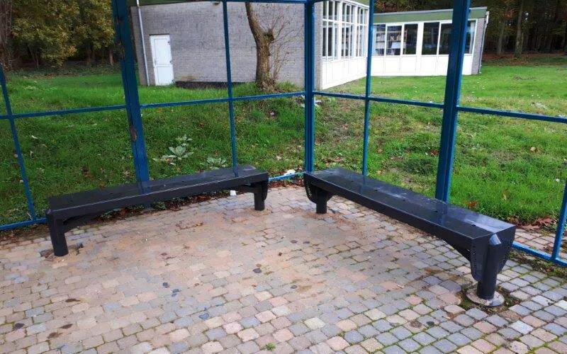
Dumaco schenkt maatwerk bankjes aan het Sprengen College
Een samenwerking met maatschappelijke meerwaarde
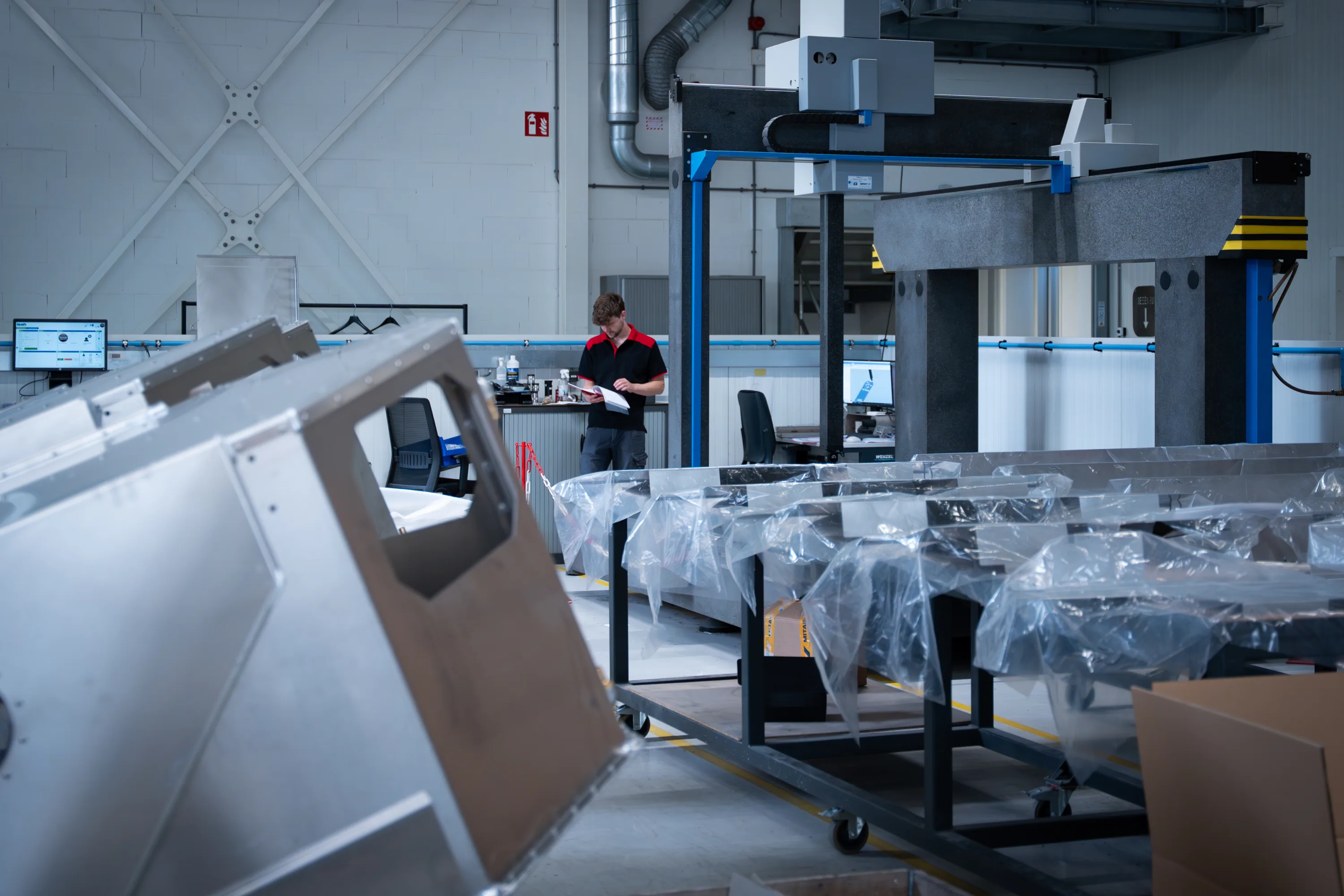
 About us
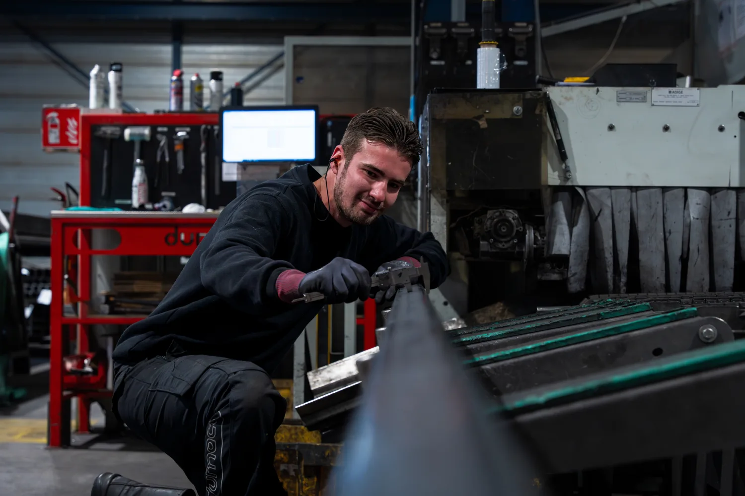
 Working at Dumaco
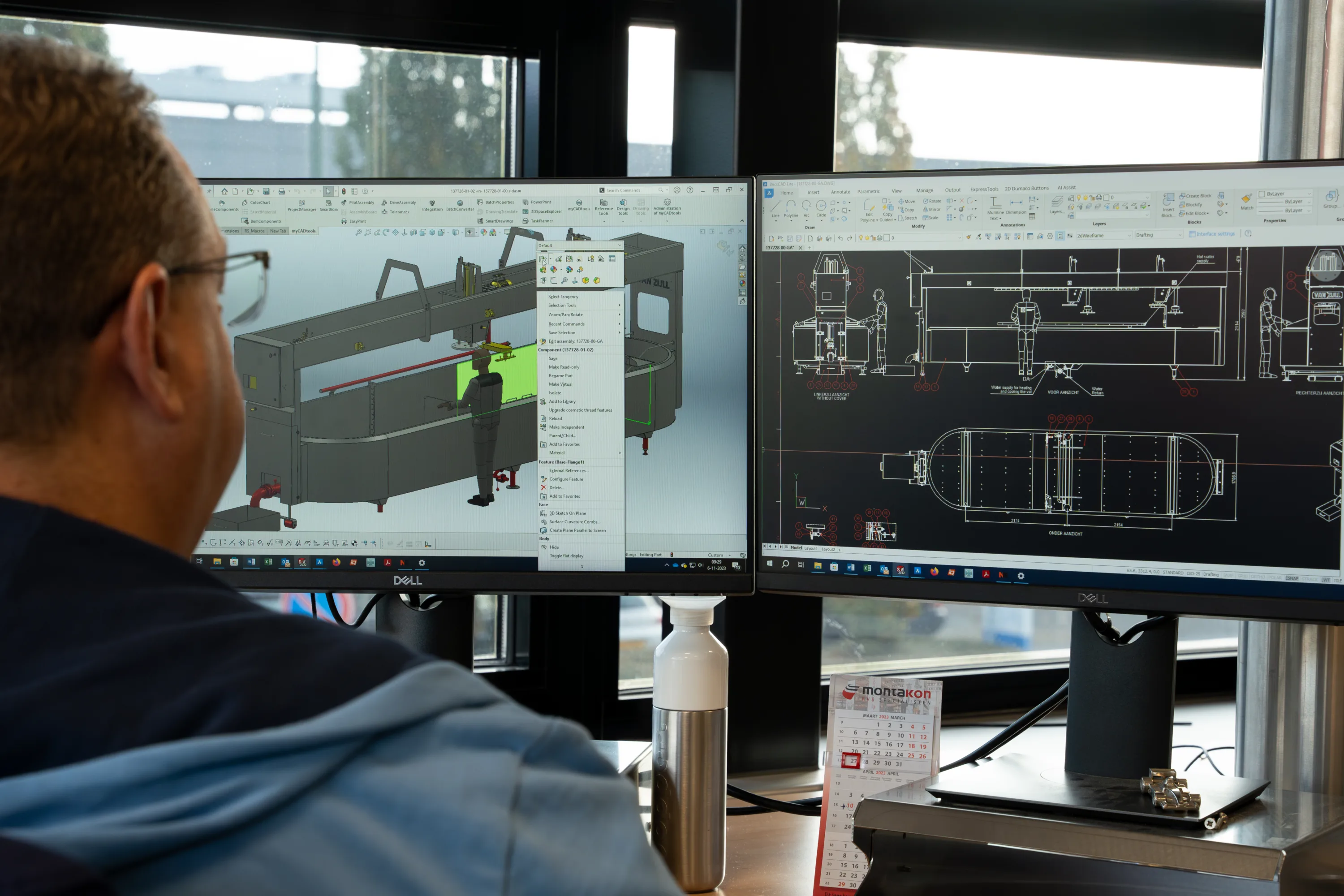
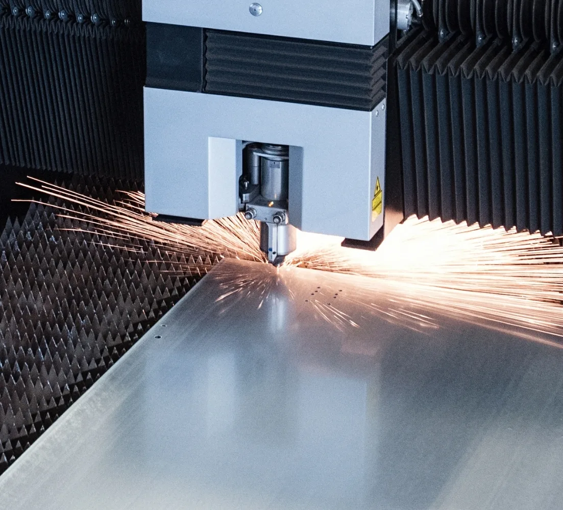
To ensure your product is produced correctly, it's important that the files you provide meet our requirements. This is the only way we can guarantee the quality and accuracy of the final product.
To ensure your product is produced correctly, it's important that the files you provide meet our requirements. This is the only way we can guarantee the quality and accuracy of the final product.
This way, you'll know exactly which specifications are needed to ensure your design is processed smoothly. By following these guidelines, you'll save time and money, prevent production errors, and receive a suitable quote and final product faster. See below for the details for submitting 2D and 3D files:
Een samenwerking met maatschappelijke meerwaarde
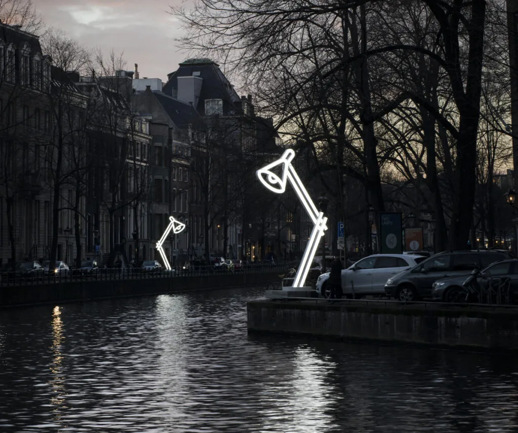
Dumaco Oss werkt namelijk sinds jaar en dag samen met kunstenaar Jeroen Henneman. De Amsterdamse beeldhouwer is o.a. bekend van De Kus in Amsterdam...
In een wereld waarin auto’s steeds zwaarder worden, blijft Donkervoort trouw aan haar filosofie: het bouwen van extreem lichte en pure sportwagens.

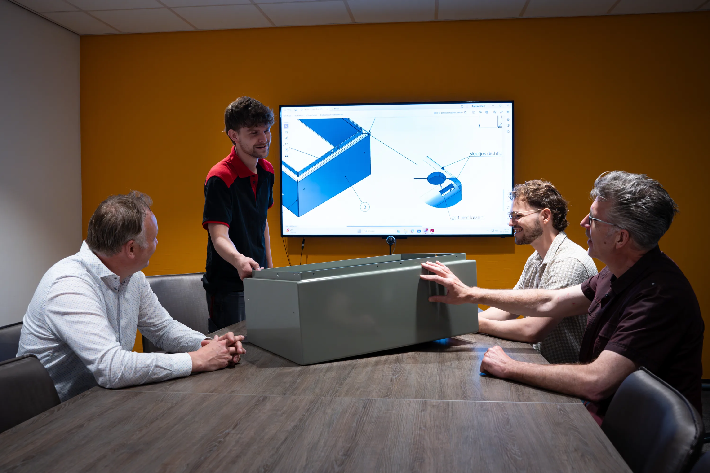
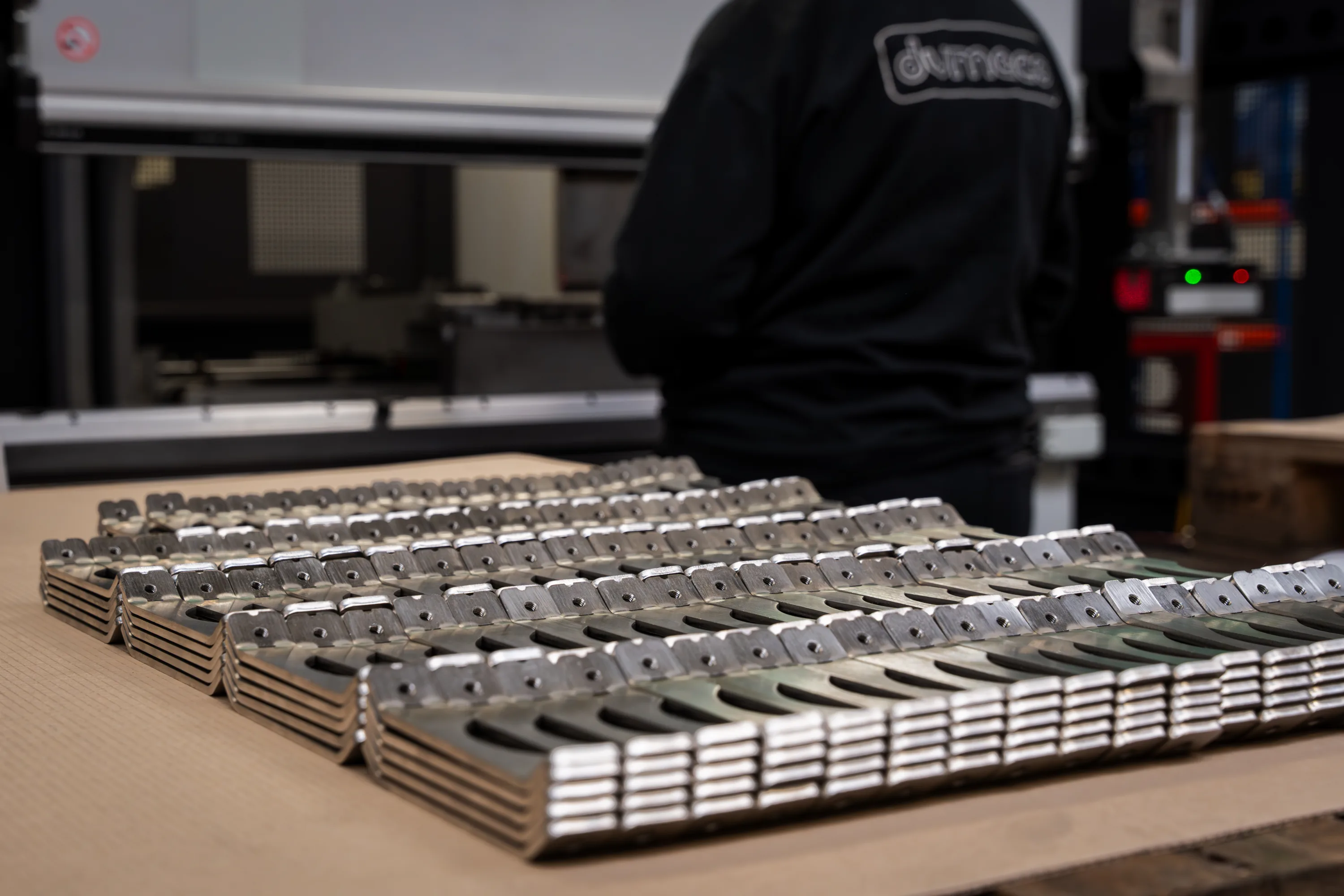
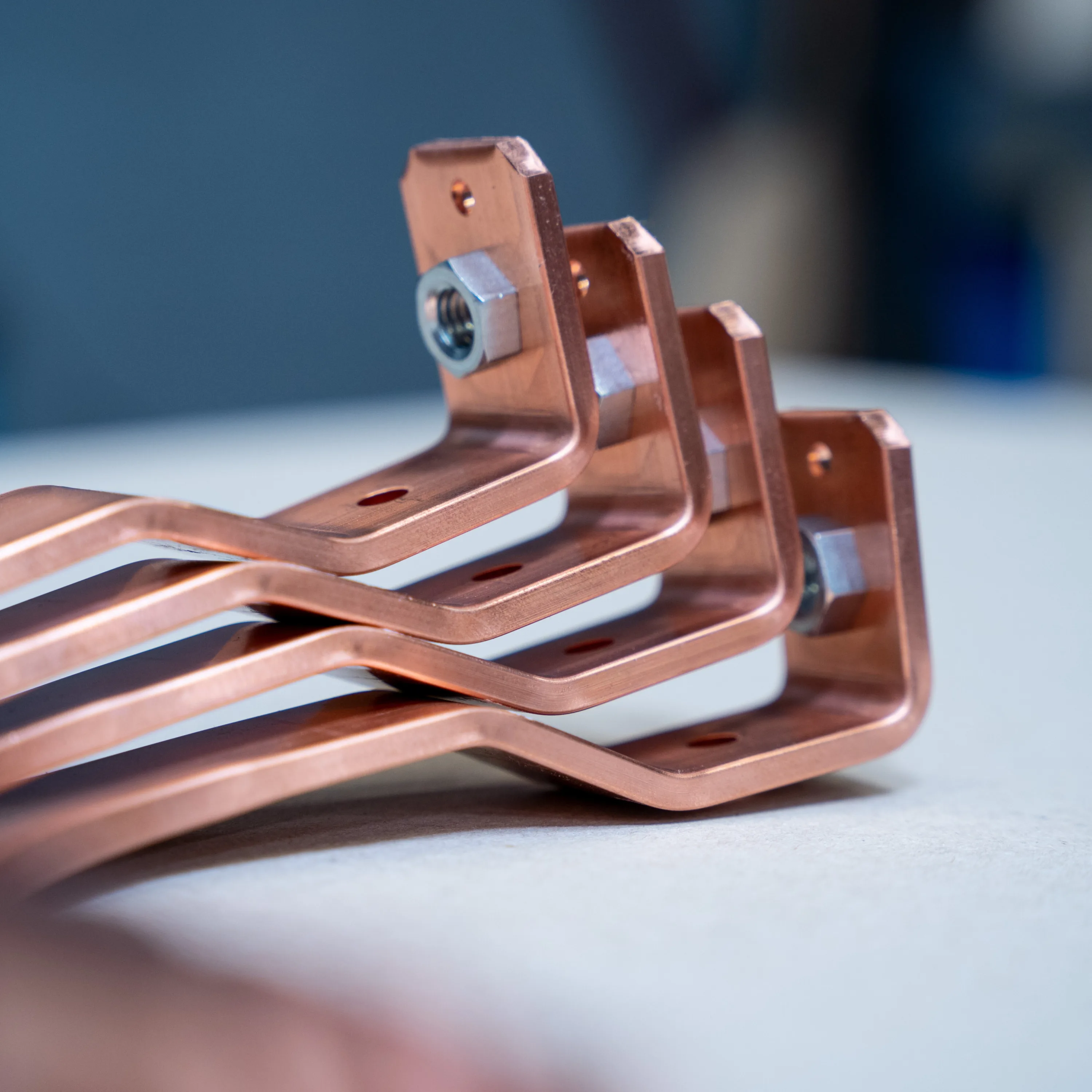
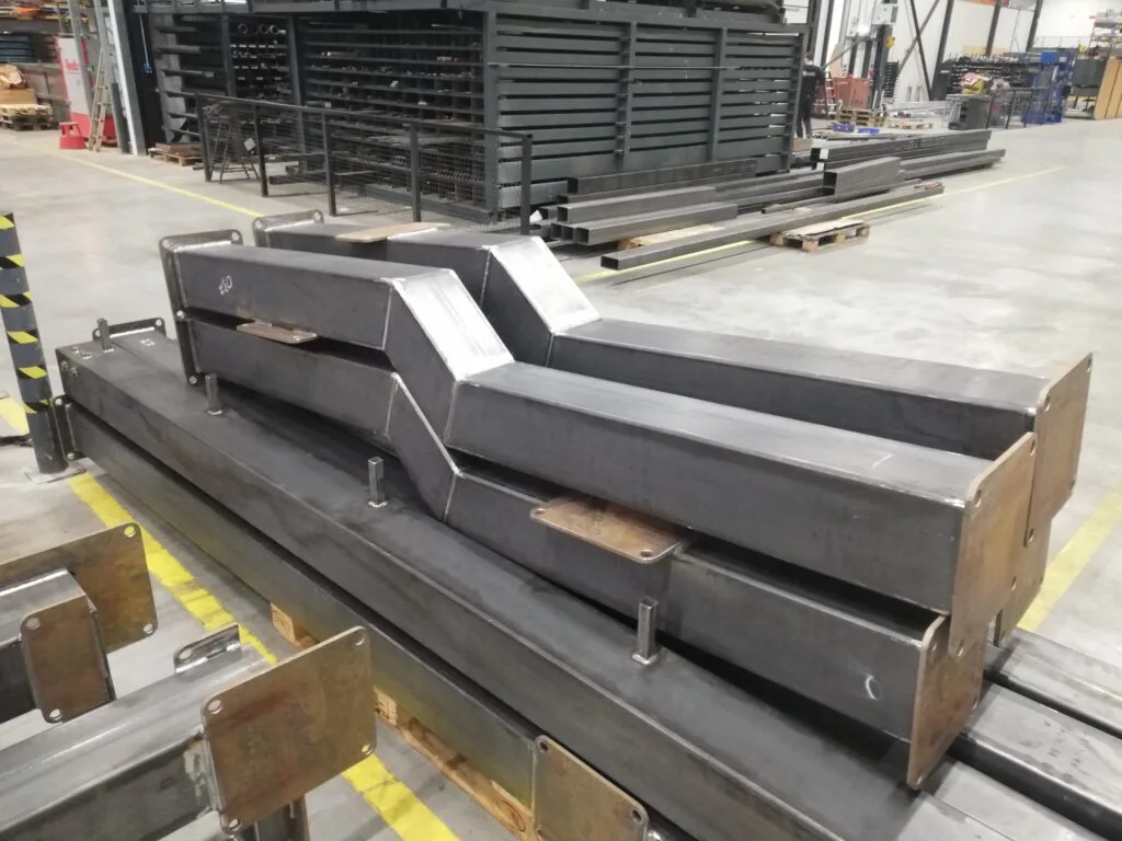
De vakmensen van Dumaco werken aan heel veel mooie projecten. Recent hebben we bijvoorbeeld deze metalen buizen gemaakt voor een klant.
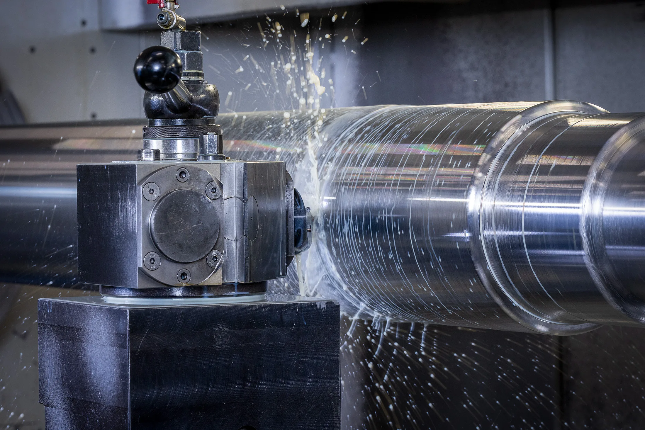
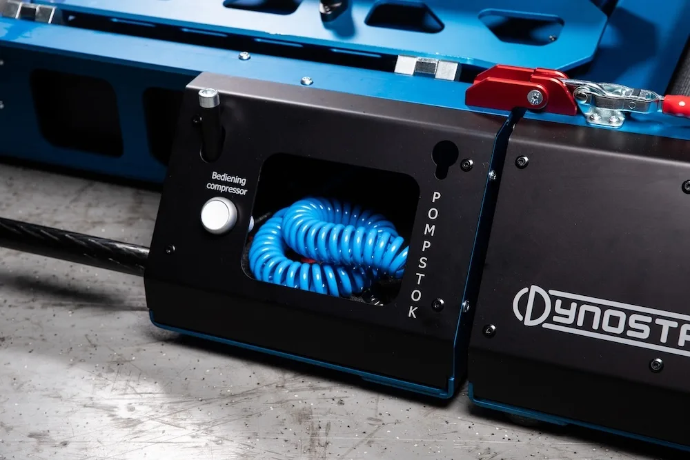
Dynostar en Dumaco werken samen aan de nieuwe rollentestbanken van de Nederlandse politie.
Dumaco levert maatwerk voor groot onderhoud Sluiscomplex Delden